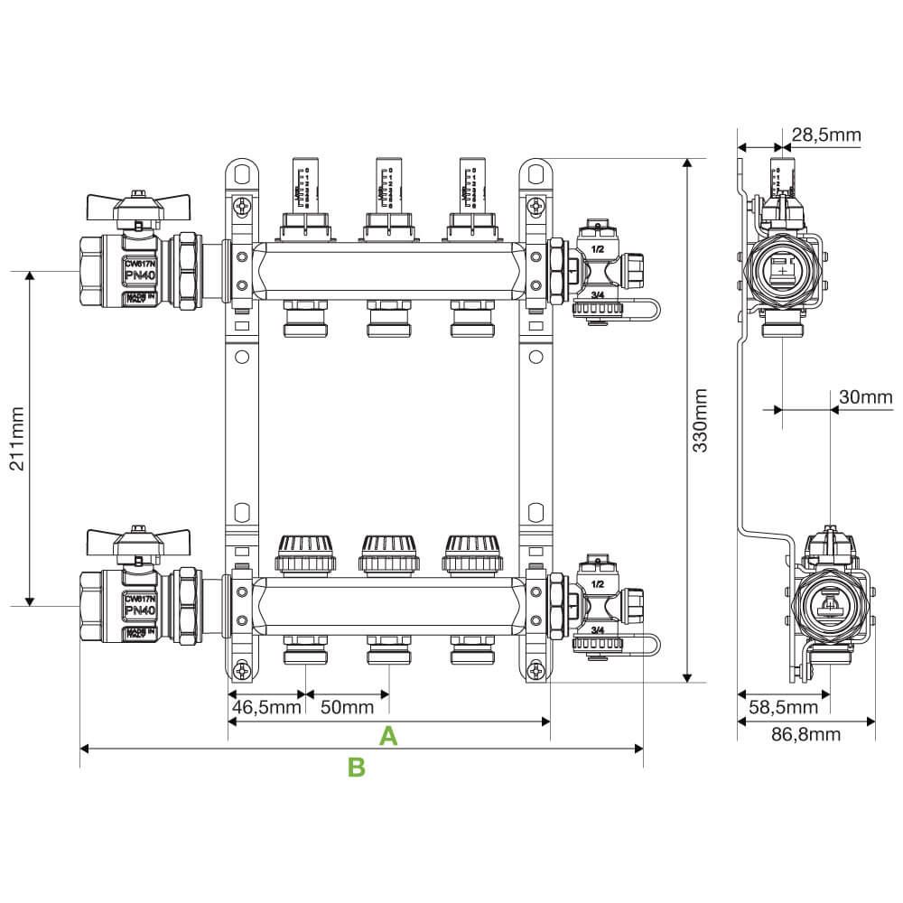
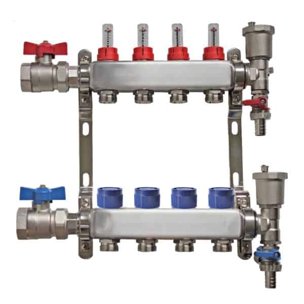
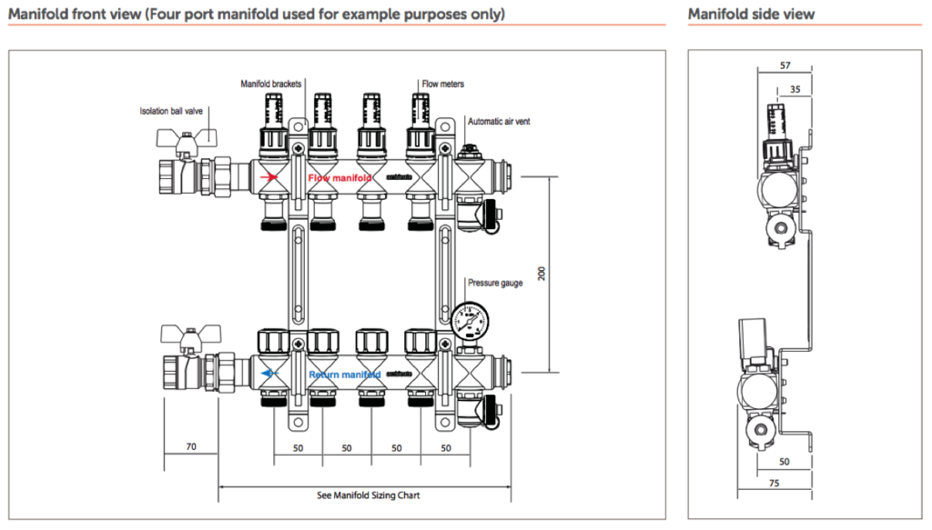
top manifold circuit, fully by rotating the blue cap on the return manifold anti-clockwise (e.g., If you open the first circuit on the flow manifold, then open the first circuit on the return manifold) 8. Open the small blue ball valve located just above the drain valve on the right side of the return manifold.. 4.2(15 reviews) Pre-assembled distribution manifold. Max. working pressure: 6 bar. Temperature range: 5-60 °C. Outlet centre distance: 50 mm. Equipped with: - return manifold with built-in shut-off valves fitted for thermo-electric actuator; - flow manifold complete with flow meters with 0-5 l/m scale and flow rate balancing valves; - end.
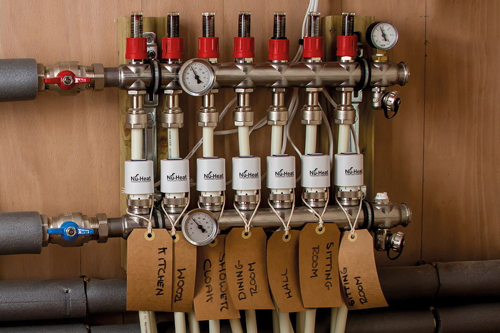
The Guide to Manifolds for Underfloor Heating NuHeat
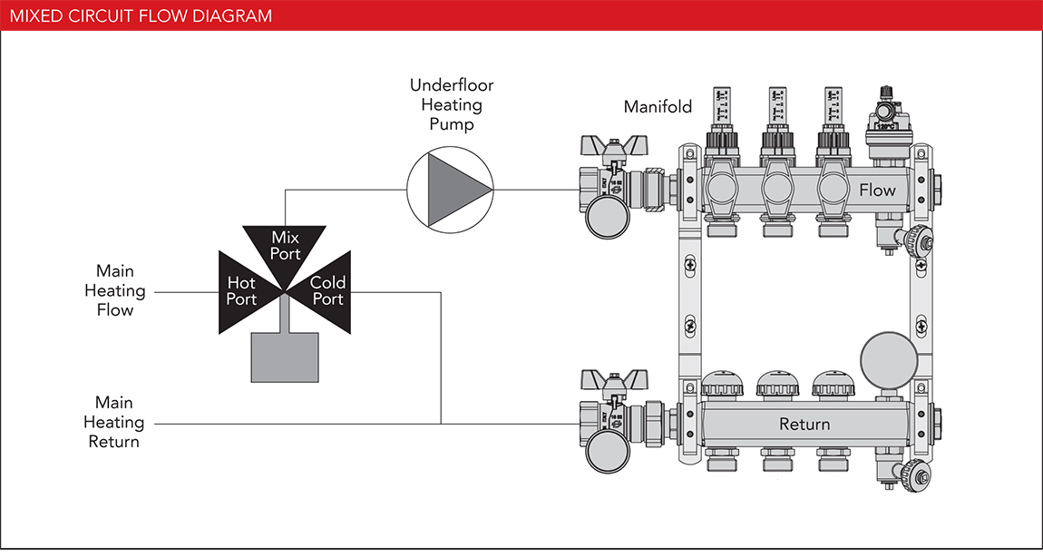
UNDERFLOOR HEATING CONTROLS by MYSON
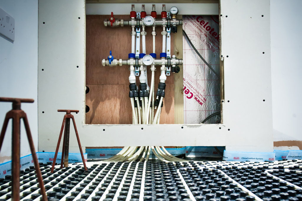
The Guide to Manifolds for Underfloor Heating NuHeat
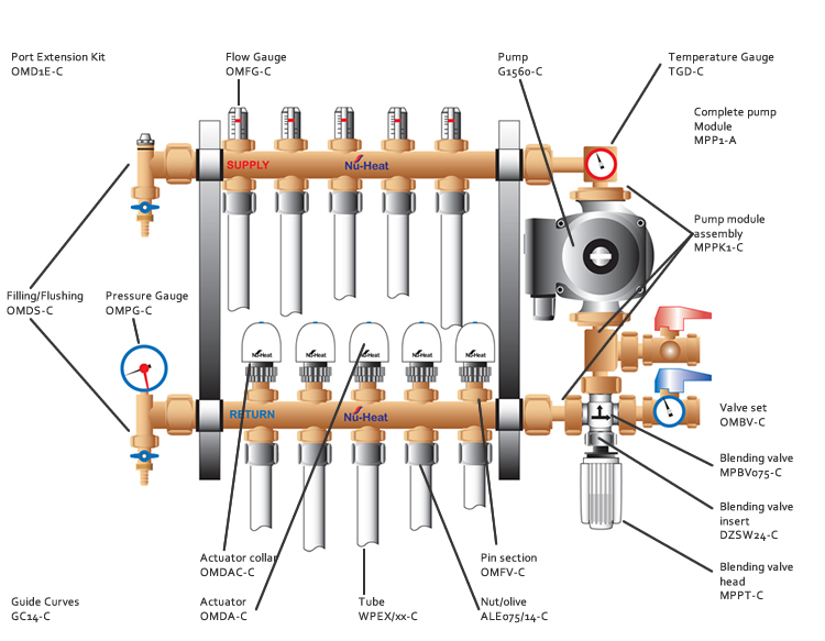
Controlling underfloor heating in passive house Underfloor Heating

Reliance Stainless Steel Standard Underfloor Heating Manifold With Isolation Valves & Pipe

Manifolds Stainless Steel Underfloor Heating Radical Heating

How Manifold Radiator Systems Work

Installer's Guide To UFH Manifolds Blogs Ambiente UFH

Nu Heat Underfloor Heating Wiring Diagram

Stainless Steel Underfloor Heating Manifold Kit with External Flow Meter , Floor Heating

Underfloor Heating Manifold Flow Meter , Heating Manifold Replacement Flow Meter

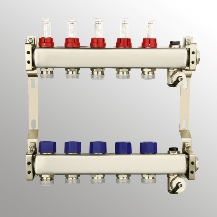
Underfloor Heating Manifold Reliance 5 Port Stainless Steel UFH Manifold Five Outlets
Radiant Heat Manifold Brass Loops 1 1/2 NPT For Domestic Hot Water System ubicaciondepersonas

Underfloor Heating Express Manifold Installation Assembly Guide YouTube
Manifolds and Mixing Set Joule
Underfloor Heating System Flow Meter Manifold Stainless Steel Manifolds
Underfloor Heating Manifold Flow Meter The Underfloor Heating Company
Installer's Guide To UFH Manifolds Blogs Ambiente UFH
UFH fault Underfloor Heating

ZYWUOY Underfloor Heating Manifold Flow Meter/Regulator PSW Trade SUPPLIERS LTD Flow Meter for
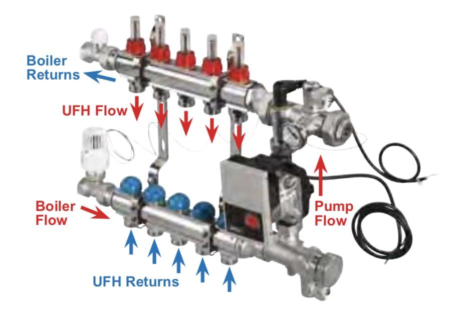
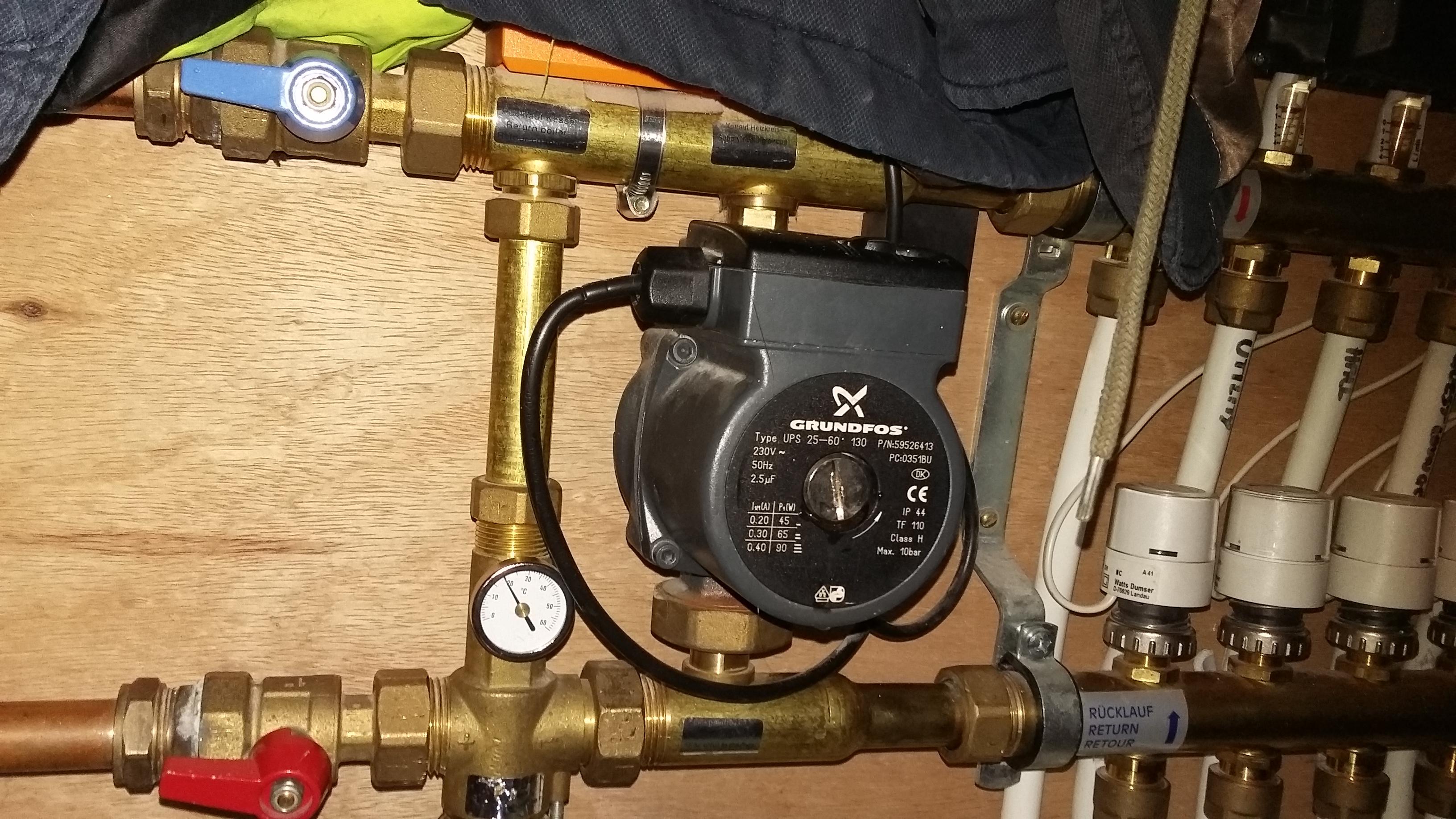
Underfloor Heating Manifold Design 1. Bracket + Bracket Spacer 2. Flow Water Temperature Sensor 3. Circulator Pump (Grundfos UPS2 25/60) 4. Thermostatic Actuator. Isolate the heating circuits on the flow and return manifold arms. 3. Carefully depressurise and then drain the manifold using the fill/drain valves, taking care to collect all of.. The components of an underfloor heating manifold. Flow Gauge: the flow gauge shows the current flow rate for the zone, and is set using the flow adjustment valve (3). The required flow rate is calculated during the design process and shown on the CAD drawings.. Pressure Gauge: the pressure gauge (7) is found on the flow return manifold rail.